Entity Relationship Diagrams (ERD)
Definition and Purpose
- An entity-relationship diagram (ERD) is a data modeling technique that graphically illustrates an information system’s entities and the relationships between those entities.
- An ERD is a conceptual and representational model of data used to represent the entity framework infrastructure.
The Elements of an ERD are:
- Entities
- Relationships
- Attributes
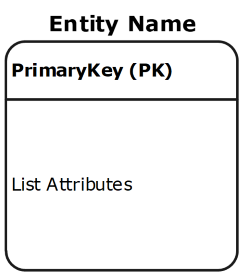
Entities
- Must balance with other diagrams – same name in system and process DFD
- An entity is a real-world item or concept that exists on its own.
- Entities are equivalent to database tables in a relational database, each row of the table represents an instance of that entity.
Relationships
- A relationship is the association that describes the interaction between entities.
- Cardinality refers to the number of instances of one entity that are associated with an instance of another entity.
- In general, there may be one-to-one, one-to-many, or many-to-many relationships.
- Ordinality relates to whether an entity is mandatory or optional with another associated entity.
| Symbol | Meaning |
|---|---|
 |
Zero or One an optional relationship |
 |
One |
 |
One and Only One |
 |
Zero or Many an optional relationship |
 |
One or Many |
 |
Many |
- Description of the relationship between two entities
- Verbs are expected here
- Can either have a label at either end or one with a “/” separating: “Can contain / is on”
- Reads from parent to child (one to many) or left to right, top to bottom
Attributes
- Also known as a column, an attribute is a property or characteristic that describes the entity that holds it.
- A primary key, also known as PK, is a special kind of entity attribute that uniquely defines a record in a database table. In other words, there must not be two (or more) records that share the same value for the primary key attribute. PK must be Unique, Stable, and NOT NULL.
- A foreign key, also known as FK, is a reference to a primary key in a table. It is used to identify the relationships between entities. Note that foreign keys need not be unique. Multiple records can share the same values.
- Must list mentioned ones from specs and need to have at least 3 per entity
Steps Involved in Creating an ERD Include:
- Identifying and defining the entities
- Determining all interactions between the entities
- Analyzing the nature of interactions/determining the cardinality of the relationships
- Determining the attributes of each entity
- Creating the ERD
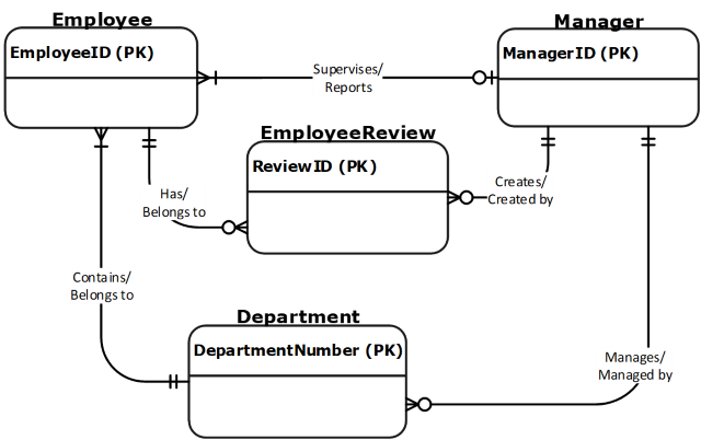
Example
- Employee
- Is part of one department
- Must belong to a department
- May or may not have a manager
- Can have 0 or many employee reviews – depending on their length of service
- Department
- Can have many employees
- Must have at least one employee to be considered a department
- A department with more than 3 employees must have a manager
- Manager
- Can manage more than one department
- Has employees
- Creates yearly performance review for every employee
- Employee review
- Must be associated to an employee
- Is created by a manager